Have you ever connected an LED to a Raspberry Pi and felt that moment of excitement as it lights up, responding to the code you just typed in? There’s something electrifying about seeing that tiny light respond right before your eyes. Now, add Pulse Width Modulation (PWM) into the equation, and you’ve unlocked a whole new level of control over your LED’s brightness. Think of it as being able to adjust the flow of water in a dam: you’re not letting too much through, but you’re also not cutting it off completely—just finding the perfect balance.
In this guide, we’ll break down what happens when you connect an LED to a Raspberry Pi using PWM, exploring each piece of this intriguing setup. By the end, you’ll have a clear understanding of how your Raspberry Pi—affectionately called “Pi”—can use PWM to adjust an LED’s brightness with precision, similar to how a dam modulates water flow.
Exploring Pulse Width Modulation (PWM) And How It Works
Pulse Width Modulation, or PWM, is a versatile technique frequently used in electronics, from controlling LED brightness to regulating motors and heating systems. In essence, PWM allows for the adjustment of power delivered to a device by varying the length of time a signal remains active during each cycle. This approach lets us efficiently control the power output—like adjusting the brightness of an LED—with minimal energy loss.
At its core, PWM works by rapidly switching a digital signal on and off. The “duty cycle,” or the percentage of time the signal stays on in each cycle, dictates the overall power delivered. For an LED, a higher duty cycle means more brightness, as the light remains active for a greater portion of each cycle, while a lower duty cycle dims it. This method is highly efficient for LED brightness control, using far less power than resistors, which is ideal for sustainable, low-energy applications.
PWM’s utility extends far beyond LED control. It’s found in various fields, powering everything from speed adjustments in electric motors to temperature control in heating devices. For projects using LEDs and a PWM setup on devices like a Raspberry Pi, understanding how PWM works is key to achieving efficient and adjustable lighting without excessive energy use. Mastering PWM techniques can significantly enhance the functionality, durability, and energy efficiency of your electronics projects.
Key Components For Connecting An Hook Up LED To Pie PWM Dam

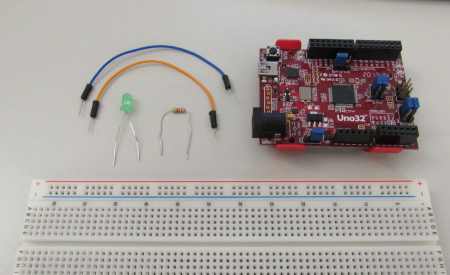
When setting up an LED with PWM on a Raspberry Pi, gathering the right components is essential for smooth operation. Each part has a unique function that contributes to the reliability and efficiency of the system.
1. LED (Light Emitting Diode)
The LED is the central element in this setup, producing light when a current flows through it. LEDs come in various colors and specifications, each with different voltage and current needs. When selecting an LED, it’s crucial to choose one that aligns with the voltage and current limitations of the PWM setup on the Raspberry Pi.
2. Resistors
Resistors play a protective role in the circuit, limiting the amount of current that passes through the LED. This helps prevent overheating and prolongs the LED’s life. Calculating the correct resistor value involves using Ohm’s Law and considering the LED’s specifications to ensure that the current is adequately controlled for safe operation.
3. Microcontroller (e.g., Raspberry Pi)
The microcontroller serves as the system’s control hub, managing the PWM signal sent to the LED. By adjusting the duty cycle of the PWM signal, the microcontroller can control the LED’s brightness precisely. The Raspberry Pi is a popular choice for this purpose due to its ease of programming and support for PWM.
4. PWM Controller
In this setup, the PWM controller regulates the power supplied to the LED by switching the voltage rapidly on and off. This precise modulation allows for smooth dimming and efficient brightness control, making it a valuable component for any lighting setup where variable brightness is required.
Together, these components form a cohesive system that allows you to control an LED’s brightness through PWM, offering a balance between power efficiency and functionality. With this setup, you’ll be equipped to customize LED brightness while preserving the longevity and performance of your electronic projects.
Understanding Piezoelectric Devices And Their Role With PWM

Piezoelectric devices are fascinating components that respond to mechanical pressure by generating an electrical charge—or conversely, they create vibrations when exposed to an electric field. They’re commonly used in electronics, especially in piezo buzzers, where an alternating voltage such as a PWM signal causes the material to vibrate and emit sound.
Using a Raspberry Pi or similar microcontroller with PWM to control piezo buzzers can produce various tones and frequencies. By adjusting the PWM signal’s duty cycle and frequency, it’s possible to create a range of sounds, making piezo buzzers ideal for alerts, alarms, and feedback in electronic systems.
How Piezo Buzzers Interact with PWM Signals
The sound produced by a piezo buzzer is directly linked to the frequency of the PWM signal it receives. A high-frequency signal generates a higher-pitched sound, while a lower frequency produces a deeper tone. Adjusting the duty cycle also influences the sound’s volume and tonal quality, giving you even more control over the output.
Step-by-Step Guide: Connecting An LED To A PWM Signal
If you’re ready to connect an LED and explore PWM control, here’s a quick guide to get started:
- Set Up the Wiring
Begin by connecting the positive leg (anode) of your LED to a PWM-capable pin on the microcontroller. Attach the negative leg (cathode) to ground through a current-limiting resistor (typically 220Ω). The resistor is essential to prevent excessive current, which could damage the LED. - Configure PWM in Code
Write a simple program to configure the PWM signal, defining both frequency and duty cycle. Adjusting these values will allow you to control the LED’s brightness. - Test and Adjust
Run the program and observe how varying the duty cycle impacts the LED’s brightness. If you’re using a higher-power LED, consider adding a transistor to handle any additional current safely.
By following these steps, you’ll be able to master PWM control and understand its applications for both LEDs and piezo buzzers, opening up a world of possibilities in electronic projects!
Practical Applications Of PWM In Everyday Technology

If you’re wondering how this technical setup applies in the real world, here are some common applications where PWM (Pulse Width Modulation) plays an essential role in enhancing efficiency and control.
- Smart Home Lighting Systems
In smart homes, lighting goes far beyond the traditional on/off switch. PWM technology allows LEDs to dim or brighten smoothly, whether through a smartphone app or voice command. By connecting LEDs to a central microcontroller like a Raspberry Pi, homeowners can create an adaptable lighting system that offers energy efficiency, convenience, and control—all managed from a single interface. - Robotics and Precision Control
In robotics, the ability to precisely control components is critical. PWM enables this by adjusting the power supplied to motors and LEDs, allowing for fine-tuned movements and responses. Using a Raspberry Pi as the brain of the robot, you can control motor speeds, LED indicators, and servo positions, creating a synchronized system that improves the robot’s performance and responsiveness. - Computer Fan Management
Computers and gaming systems often rely on PWM to control fan speeds, especially during demanding tasks like video editing or gaming. PWM adjusts the fans based on temperature, keeping the system cool without always running the fans at maximum speed. This keeps noise levels down and extends fan life, while providing effective cooling only when it’s needed. - Audio Systems
PWM also has applications in audio technology, where it helps control speaker volume with high precision. Modulating the signal with PWM allows for smooth volume adjustments without sacrificing sound clarity, enhancing the listening experience in devices like headphones, speakers, and home audio systems.
Each of these real-life examples demonstrates how PWM brings efficiency, control, and flexibility into various devices and systems, making it a vital tool in modern electronics.
What Is “Hook Up LED To PWM” Anyway?
You may have heard the term “hook up LED to PWM” (Pulse Width Modulation), and it sounds like complex engineering lingo—but it’s actually a simple way to control the amount of power delivered to a device, like an LED, by adjusting the “on” time in a repeating electrical signal.
Think of it like controlling water flow in a river with a dam. If you want a stronger flow, you open the gates wider; for less, you narrow them. Similarly, PWM modulates the “flow” of current to the LED, allowing precise control over brightness by adjusting how long it stays “on.”
Breaking Down The Dam Analogy For PWM Control
Imagine you’re managing the brightness of an LED by opening and closing the “gates” of electrical current. In this analogy, PWM is the tool that manages the “flow.” The LED’s brightness depends on how much time it’s allowed to stay lit during each cycle. A longer “on” pulse (high duty cycle) results in a brighter LED, while a shorter “on” pulse (low duty cycle) makes it dimmer. This rapid switching on and off creates the appearance of steady brightness.
- High Duty Cycle = Bright LED: A higher “on” time in each cycle leads to a brighter LED.
- Low Duty Cycle = Dim LED: A shorter “on” time results in a dimmer appearance.
This modulation pattern creates a smooth illusion of continuous light by rapidly turning the LED on and off.
Troubleshooting Guide For PWM-Driven LED And Piezo Projects

Working with PWM-controlled LEDs and piezo elements on a microcontroller can be both exciting and challenging. However, if your components aren’t working as expected, don’t worry—these common troubleshooting tips should help you identify and fix the issues.
1. LED Not Turning On
If your LED isn’t lighting up, there are several points to check to get it glowing.
- Double-Check Connections
Start by ensuring all your connections are secure. The LED’s anode (positive leg) should be connected to the microcontroller’s PWM pin, and the cathode (negative leg) should be properly grounded through a resistor. Loose or incorrect connections are often the root cause when LEDs fail to light up. - Verify Resistor Value
Using the right resistor is crucial. If the resistor value is too high, the LED might be too dim or not light up at all. If it’s too low, there’s a risk of overloading and potentially damaging the LED. Check the LED’s forward voltage and recommended current, and calculate the resistor value accordingly using Ohm’s Law (R = V/I). This will help ensure safe and proper functioning of the LED. - Power Supply Check
Confirm that the power supply is active and providing the correct voltage for your circuit. Sometimes, using an external power source for the LED may be necessary, especially if your setup includes multiple components.
2. Piezo Element Not Producing Sound
If the piezo element isn’t making any sound, consider these potential issues:
- Verify PWM-Capable Pin
Ensure that the piezo element is connected to a PWM-capable pin on your microcontroller, as not all pins support PWM output. Consult your microcontroller’s documentation to confirm which pins offer PWM capability, as this will allow for proper tone generation. - Check the Code for Accuracy
Review your code for any errors, particularly in sections where the frequency and duty cycle are set. If there are syntax errors or incorrect frequency values, the piezo element may not vibrate at all. Pay attention to any specific functions or libraries used for tone generation, and make sure they are correctly implemented. - Inspect for Physical Damage
Piezo elements are relatively fragile, and even minor physical damage can impair their functionality. Ensure the element is in good condition, without cracks or other signs of wear that could affect sound production.
3. Inconsistent LED Brightness
If your LED brightness appears to fluctuate or is not steady, here are some possible solutions:
- Adjust the PWM Frequency
Inconsistent brightness can often result from a low PWM frequency. Experiment with increasing the PWM frequency in your code until you reach a stable brightness level. Some LEDs require a higher frequency to maintain consistent brightness, especially if you notice flickering. - Check for Voltage Stability
A fluctuating power supply can cause brightness inconsistencies. If you’re using a battery, ensure it has adequate charge, or consider switching to a more stable power source. Voltage fluctuations are more common with batteries that are nearly depleted. - Confirm Microcontroller Processing Speed
In cases where the LED is part of a complex circuit, the microcontroller may be managing multiple tasks simultaneously. If the microcontroller is overloaded, this can affect PWM output consistency. Try simplifying the code or offloading some tasks to another microcontroller if possible.
Additional Troubleshooting Tips
- Inspect Circuit Grounds
Poor grounding can lead to various issues in your setup, including erratic LED performance and irregular piezo sounds. Make sure all ground connections are solid, with minimal resistance between the ground and other components. - Run Diagnostic Tests in Stages
When troubleshooting, try isolating each part of the system. For example, test the LED and piezo element separately to ensure they work independently before integrating them with the PWM controller. This approach can help identify whether an issue is within the component itself or in the code and connections.
By following these tips, you can identify and resolve common issues, enhancing both the performance and reliability of your PWM-controlled LED and piezo projects.
FAQs About Hook Up LED to Pie PWM Dam
1. What is Pulse Width Modulation (PWM)?
- Answer: PWM is a technique for controlling the power sent to electronic devices by rapidly switching the power on and off. By adjusting the “on” time (duty cycle) in each cycle, PWM allows for precise control over devices like LEDs, motors, and more.
2. Why use PWM with an LED?
- Answer: PWM allows you to control the brightness of an LED by modulating how long it stays on in each cycle. This method is efficient and provides smooth brightness adjustment without using excessive power.
3. Why is the Raspberry Pi a good choice for PWM projects?
- Answer: The Raspberry Pi is versatile and easy to program, making it ideal for handling low-level tasks like PWM control. It can support complex systems while being accessible for beginners and experienced users alike.
4. What do I need to control an LED with PWM on a Raspberry Pi?
- Answer: You’ll need a Raspberry Pi, an LED, a resistor (usually around 220Ω), and the appropriate Python libraries installed to program the GPIO pins for PWM control.
5. Can PWM be used for applications other than LED brightness control?
Conclusion
PWM (Pulse Width Modulation) is an incredibly useful tool for controlling devices like LEDs with precision and efficiency. Through adjusting the duty cycle, PWM enables smooth, gradual brightness changes that would be difficult to achieve with basic on/off switches alone. Using a Raspberry Pi to implement PWM control adds flexibility and opens up a world of possibilities, from simple LED dimming to more complex applications like robotics and smart home lighting.
By following the setup guide and using the sample code provided, you can gain hands-on experience with PWM and understand how it influences electronic devices in real-world applications. Whether you’re a beginner learning about electronics or an experienced maker, PWM on the Raspberry Pi is an excellent project that combines theory with practical skills. With this knowledge, you’ll be better equipped to explore further projects and expand your capabilities in electronics and programming.


